civil 3d change template of auto open drawing
Getting Productive with Programme Product Tools in Ceremonious 3D
By Sam Lucido for Autodesk University

Design projects can become challenging when working with large sites which include lengthy roadways and site features that are needed to be displayed on multiple sheets for product. With the plan production tools in AutoCAD Ceremonious 3D you lot tin can automate the process of creating programme and contour sheets quickly. Nosotros will explore how to employ these tools to create multiple plan and profile sheets, sections on multiple layouts, and necktie it all together in a sheet set set for publishing your deliverable. Permit'south get productive and acquire how to optimize the product of final plans and profile drawings.
Introduction
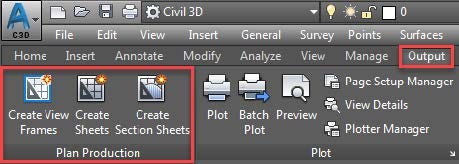
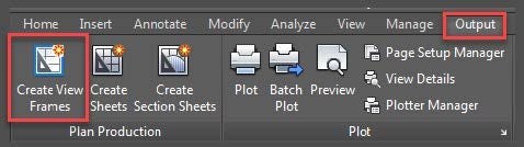
How do y'all efficiently create your final plans quickly and easily for press in AutoCAD Civil 3D? The plan and production tools will assistance yous quickly create sheets that automatically display station ranges of alignments and profiles in your plans. These wizards volition also Create View Frames, Plan and Profile Sheets, and Department Sheets, all of which will automatically display segments of alignments, profiles, sections, and plan sheets in your design fix. The effigy below shows the Plan Production Tools located on the Output tab of the Ribbon.
You have been working on your design project for weeks and running prints for review supplying to the engineering team to check scale and the project details. We have now washed the planning and information technology is fourth dimension to produce our sheets at a scale for a deliverable. Before you first generating all sorts of sheets yous must address a few concepts and prerequisites. The Plan Production features draw on several Civil 3D components to create a plan set.
Nosotros will brainstorm with the drawing templates. Programme product tools create new layouts for each sheet in a plan prepare at a scale. Therefore, yous have to set upwardly templates with named viewports at each scale telling Ceremonious 3D what you would like to produce. Most features in Ceremonious 3D have styles which nosotros will define those within our template.
Steps to follow while referencing this textile:
- Create the templates (yous can start with the templates provided from Autodesk)
- Use these as a guide to develop your own templates with your company title cake
- Select the Create View Frames (shown in the figure above)
- Choose your sheet type and the template with the appropriate calibration
- Cull View Frame Groups and Match Line Styles
- Change those (and add together additional subsequently selecting)
- If you lot chose a profile you volition have to select the Contour and Band Styles (as with View Frames, you tin can change these afterwards)
- Profile Views can play an important function in "white space" around your profile
- Select the Create Sheets (shown in the figure above)
- Define your Sheet Prepare (new or existing; use Sheet Sets to your advantage)
- Add any Data References (simply if y'all are creating a new drawing file)
- Select Create Sheets and the process will brainstorm to create your new layouts
Related: Managing Your Sheets with the Sheet Ready Manager with Sam Lucido
Overview
Instead of manually creating many viewports on layouts to show segments of alignments, you tin can create view frames that automatically capture predefined areas forth an alignment. View frames are rectangular areas forth an alignment that represent what is displayed in the associated viewports on the layouts (sheets) to be created. This automation saves yous from making many manual changes when your blueprint data changes. Remember the days when you lot created view frames to match the calibration of your pattern?
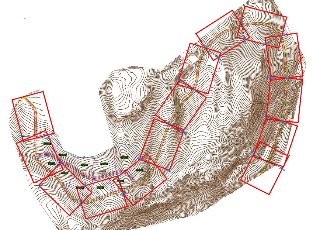
The image in a higher place shows an alignment of a long road with curves. The red boxes are the view frames that nosotros are requested to show the road on Plan sheets with or without a profile.
By setting upwardly the Due north Arrow and Scale on your templates y'all also have the ability to have that Northward Arrow linked to the viewport giving it the ability to rotate to "true North" when the view changes throughout your sheets.
Templates
Several predefined template (.dwt) files are provided with Civil 3D 2018. You must have templates created to follow the four scenarios every bit shown beneath. For this demonstration we have templates created for each instance every bit shown.

Program(s) Only
The current drawing must contain an alignment.
You must be able to admission a template that contains a viewport with a Viewport Type defined as Program, such equally the Civil 3D (Imperial) Plan Only.dwt or the Civil 3D (Imperial) Plan over Plan.dwt template located in the Template\Program Production folder.
Contour(s) Only
The current drawing must contain an alignment and a profile.
You must be able to admission a template that contains a viewport with a Viewport Type defined as Profile, such as the Ceremonious 3D (Majestic) Profile Only.dwt or the Ceremonious 3D (Imperial) Contour over Profile.dwt template located in the Template\Plan Production folder.
Program and Profile
The current drawing must contain an alignment and a profile.
You must be able to access a template that contains a viewport with a Viewport Type divers as Plan, and a viewport with a Viewport Type divers as Profile, such as the Civil 3D (Imperial) Plan and Profile.dwt template located in the Template\Plan Production folder.
Department
The current drawing must contain an alignment, sample lines, and cross sections. Y'all must exist able to access a template that contains a viewport with a Viewport Blazon defined as Section, such as the Civil 3D (Imperial) Department.dwt template located in the Template\Program Production folder.
Templates and Viewports
We first will create our template file using specific Programme and Product Viewports. Open a championship block drawing that you utilise for your visitor standard. The file you should be using volition be in paperspace on a layout tab. This is the file where y'all ascertain your sheet set properties which contain project-specific data that will exist carried throughout the project.
Nosotros will now create the viewports. On the Contextual Ribbon Layout Tools Tab select Named under the viewports panel as shown. Notice how my layer is besides fix to my viewport layer. When you are cartoon the viewports, they will be placed on the right layer.

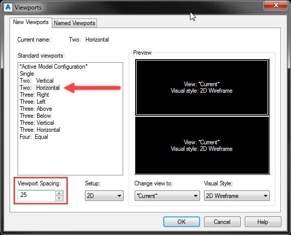
In this example, nosotros will create two horizontal viewports for a plan and profile scenario. We will select two horizontal viewports with a spacing of 0.25 between them. If I was to create a Plan only, I would select one viewport.
Subsequently placing the viewports in your cartoon, you lot must prepare the Viewport type. Open up your properties palette (CTRL+1) to see the backdrop of the viewport. Select the viewport and move to the viewport blazon and designate the advisable viewport that you need for the template. You can modify the properties of the viewport inside the template file to ensure that you have the proper settings for your standards.

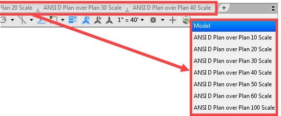
Once y'all take your layout type correct, you lot will need to make sure the scale is correct on the viewports and name a sheet (layout tab) to reference the correct calibration and type as shown.
The final step of completing the template is to make sure y'all have a N pointer and scale bar added to your sheets. You lot will accept the options to select the Northward arrow block when creating the sheets in the plan and product tools to ensure the alignment is correct.
Plan Product Commands
You tin admission the plan product commands from the Output tab and Plan Production contextual tab on the ribbon as shown above. The Plan Production contextual tab is displayed when you lot select a view frame or a friction match line in the drawing.
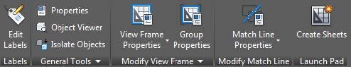
The following definitions are taken straight from the Autodesk Knowledge Network and give a good description of the general commands.
Create View Frames Wizard — Commencement the process of using the plan production tools by using this wizard to ascertain a group of view frames forth an alignment.
View Frame Grouping — The view frame group object helps you manage a single group of view frames that are displaying sequent station ranges forth the same alignment. Yous tin can set many options at the view frame group level, such as styles and labeling. View frame group objects are displayed in the Prospector tree, and you can command their default command settings in the Settings tree.
View Frames — View frames are rectangular-shaped regions forth an alignment that ascertain an area that will be displayed in a sheet. The view frame size, shape, and scale come from a designated viewport that exists on the layout tab of a specified template. After view frames are created, the backdrop of the view frame objects are saved in the currently open drawing. The view frame objects are displayed in the drawing and in the Prospector tree, and yous can control their default style and labeling in the Settings tree.
Match Lines — In the Civil 3D plan product features, a match line is a straight line that indicate locations in a view frame grouping where one view frame intersects or matches upwards with some other view frame. Match lines are only displayed in paper space and only in program view. They are designed to visually indicate the locations (first and cease stations) along an alignment where each view frame begins and ends. Friction match lines have their own object mode and they typically include labels that can identify both the previous and next sheet (view frame) along an alignment. You have the option to include a left side match line label, a right-side lucifer line label, both, or none, and you tin can cull where along the lucifer line y'all want the characterization to be displayed (meridian, middle, end of friction match line). Like view frame objects, friction match line objects are besides displayed in the Prospector tree, and you tin can control their default way and labeling in the Settings tree.
Create Sheets Sorcerer — After you take used the Create View Frames wizard, the next step is to use the Create Sheets wizard to chop-chop create your sheets. Afterward you accept created view frames and sheets for publishing in the sheet set manager.
The table below is from the Autodesk Noesis Network and lists the plan product tool AutoCAD Ceremonious 3D commands and briefly describes their functionality. Y'all can blazon in the command at the control line to start the function in Civil 3D.

Create View Frames
Using the View Frames Wizard, view frames are created automatically. View frames are always associated with a parent view frame group.
View frames are created based on an alignment in the drawing, and on a designated program view or profile view viewport in a template. In one case the View Frames are created they volition be automatically associated with a View Frame Group. and are displayed in the drawing also as in the Prospector tree. When you chose to insert match lines, the match line objects are also displayed in the drawing and in the Prospector tree.
Most of the view frame object information is derived from the viewport information specified in the template. For example, the view frames you lot create become their size and scale from the viewport in the template. Similarly, the sheet layout is also derived from the referenced template. Viewports in the referenced template must have the Viewport Type property specified, depending on the type of data you want that viewport to display. Although y'all can move or rotate view frames, you cannot change the size of a view frame. This is because the view frame'south size is based on the size of the viewport it references in the associated template.
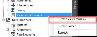
Before you create view frames, the desired alignment must already be in your drawing. Depending on the type of sheets you want to produce (programme and profile or profile merely), you may also need to have a profile already created. On the Output Tab of the Ribbon under the Plan Production Panel Select Create View Frames or correct click view Frame Groups nether prospector as shown in the figures below.
Annotation: Make certain you set the annotation scale to match the scale you will be creating for your viewports. Best practice is to set the calibration prior to creating the view frames.
Want more? Download the full class handout to continue stride past step: choose an alignment, create sheets and profiles, and much more than.
Sam is a CAD services managing director and senior civil designer with Haley & Aldrich, Inc . Within these roles he presents workshops on CAD standards, tools, and productivity techniques to managers and users in both corporate and classroom settings. He provides back up on a wide diverseness of architectural, civil, mechanical, and structural design projects. Sam has over 25 years of experience involving production design and drafting, user support, and standards coordination. He continues to be very self-motivated and enjoys working in a team surround to accomplish projection objectives on fourth dimension and with loftier quality. Sam shares his knowledge through the AKN (Autodesk Knowledge Network) and has authored 12 manufactures in AUGIWorld from 2011 to 2018. Sam is the possessor and operator of CADproTips.com and is professionally certified in AutoCAD.
Source: https://medium.com/autodesk-university/getting-productive-with-plan-production-tools-in-civil-3d-c2a60291ce45
0 Response to "civil 3d change template of auto open drawing"
แสดงความคิดเห็น